Baishicheng Hydraulic Engineering Team | Technical Content Contributor | Published September 16, 2026
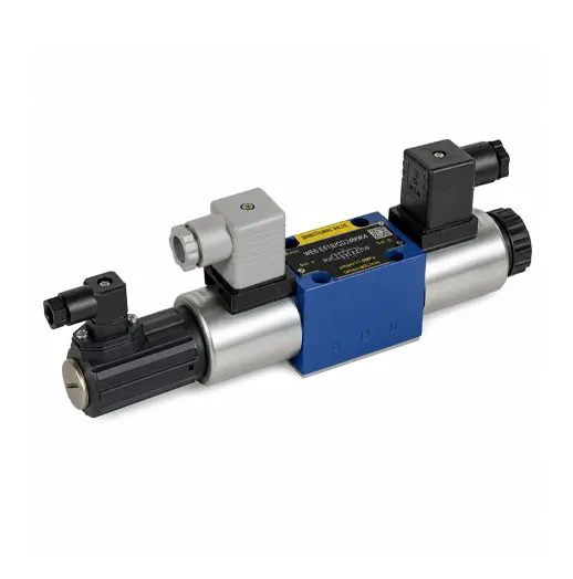
A hydraulic solenoid valve uses an electromagnetic coil to move an internal spool, opening, closing, or redirecting hydraulic fluid between different ports. By converting an electrical control signal into hydraulic switching action, the valve controls the direction, start, stop, or unloading function of a hydraulic circuit.
In a typical industrial hydraulic system, a solenoid-operated directional valve determines whether pressurized oil extends or retracts a hydraulic cylinder, reverses a hydraulic motor, stops actuator movement, or returns pump flow to the reservoir. This combination of electrical control and fluid power makes hydraulic solenoid valves important components in automated machinery, hydraulic power units, production lines, presses, machine tools, mining equipment, and custom hydraulic systems.
The basic operating principle is simple: energizing or de-energizing the solenoid changes the position of the spool. However, selecting the right valve requires more than choosing a port count. Buyers and hydraulic engineers must also consider the number of spool positions, center configuration, actuator type, coil voltage, pressure rating, required flow, port size, mounting interface, contamination level, response requirements, and the intended fail-safe behavior.
How a Solenoid Valve Actually Switches Flow
Inside a hydraulic directional control valve, a precisely fitted spool moves within a machined valve bore. The valve body contains several internal passages connected to common hydraulic ports:
- P connects to the hydraulic pump or pressure supply.
- T connects to the hydraulic tank or return line.
- A and B connect to the hydraulic actuator, such as the two sides of a double-acting hydraulic cylinder.
When the solenoid coil receives the specified electrical signal, it generates a magnetic field. That magnetic force moves an armature or plunger, which shifts the valve spool directly or operates a pilot stage. As the spool changes position, machined lands and grooves connect different combinations of the P, T, A, and B ports.
For example, one spool position may connect P to A and B to T. Pressurized hydraulic oil then enters one side of the cylinder while oil from the opposite side returns to the tank, causing the cylinder to extend. When the spool shifts to the opposite position, the valve may connect P to B and A to T, reversing the fluid flow and retracting the cylinder.
This is why a hydraulic solenoid valve is also described as an electrically operated hydraulic valve, electro-hydraulic directional valve, electric over hydraulic control valve, or solenoid-operated reversing valve. The electrical system sends the command, while the hydraulic valve controls the actual fluid path and actuator movement.
Smaller valves may use direct solenoid actuation, where the electromagnetic force moves the main spool directly. Valves designed for higher flow may use pilot operation, where the solenoid controls a smaller pilot stage that uses hydraulic pressure to shift the main spool. The correct design depends on the hydraulic circuit, required flow, response characteristics, available pilot pressure, and equipment operating conditions.
When electrical power is removed, the valve’s response depends on its spool and actuator arrangement:
- A spring-return valve moves back to its defined normal position.
- A spring-centered valve returns to the center position.
- A detented valve may remain in its last selected position.
- A double-solenoid valve may use separate coils to command opposite spool positions.
The hydraulic circuit designer must determine what the actuator should do after a power loss. Depending on the machine, it may need to stop and hold, unload pump flow, return to a safe position, or remain in the last commanded state.
4/3 vs 4/2-Way Configurations: What Changes in the Circuit
The numbers in “4/3-way” and “4/2-way” describe the valve’s number of ports and spool positions.
The first number indicates the number of working ports. The second number indicates the number of available spool positions.
A 4/2-way hydraulic valve has four ports and two switching positions. It normally provides two controlled flow paths:
- P to A and B to T
- P to B and A to T
Because a 4/2 directional valve has no third center position, its normal state must be defined by its spring return, detent, or solenoid arrangement. It is commonly used when an actuator only needs two operating directions and does not require a separate neutral spool position.
However, saying that every 4/2 valve continuously drives the actuator would be too broad. Actual actuator movement still depends on pump operation, circuit pressure, load conditions, downstream restrictions, and the valve’s normal position.
A 4/3-way hydraulic valve has four ports and three spool positions. The two outer positions normally control forward and reverse actuator movement, while the third position provides a neutral or center state.
The center position has a major effect on hydraulic system performance. Common center configurations include:
- Closed-center: P, T, A, and B are blocked. The actuator ports are isolated, although reliable load holding may still require a check valve, counterbalance valve, or dedicated load-holding valve.
- Open-center: The ports are interconnected in the center position, allowing low-resistance circulation and potentially allowing actuator movement, depending on the exact spool symbol and circuit.
- Tandem-center: P connects to T while A and B remain blocked. Pump flow can return to the reservoir while the actuator ports remain isolated.
- Float-center: A and B connect to T while P is blocked. The actuator can move more freely under an external force because both actuator lines can discharge to the return circuit.
This makes open center vs closed center hydraulics an important design decision rather than a minor valve specification. The center configuration affects pump unloading, heat generation, energy consumption, actuator holding, pressure buildup, and machine behavior during standby.
Selecting the wrong spool center can cause symptoms such as cylinder drift, unexpected actuator movement, excessive oil temperature, pump loading at neutral, slow response, or failure to hold a suspended load.
Before selecting a 4/3-way directional valve, the buyer should provide the intended actuator behavior at neutral, the hydraulic pump type, the presence of accumulators, the load direction, and whether several valves share the same pump.
Solenoid-Operated Directional Valves in Baishicheng’s Component Line
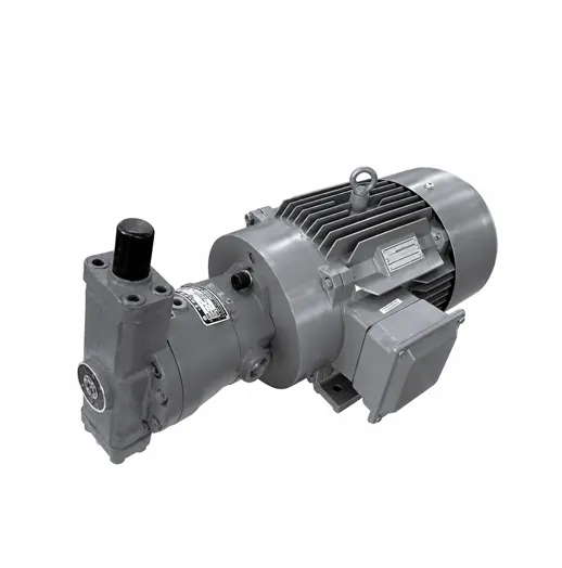
Baishicheng Hydraulic’s hydraulic components product line includes solenoid-operated directional valves, solenoid-operated pressure relief valves, high-pressure piston pump and motor assemblies, electric motors, and custom hydraulic manifold assemblies.
The company’s High-Performance Solenoid-Operated Directional Valve is used to control the direction, start, stop, and switching of hydraulic oil flow in industrial hydraulic systems. It can be integrated into hydraulic power units, hydraulic valve manifolds, automation equipment, production machinery, and application-specific hydraulic control systems.
Baishicheng does not publish one standardized voltage, pressure, flow, or port-size range for every solenoid valve application. The components are selected and integrated according to the operating requirements of the complete hydraulic system.
Buyers searching for a hydraulic solenoid valve or hydraulic control valves for sale should therefore provide more than a general valve name. Useful RFQ information includes:
- Required valve function
- 4/2-way or 4/3-way configuration
- Required center position
- Hydraulic circuit diagram
- Coil voltage and electrical connector
- Maximum working pressure
- Required flow rate
- Hydraulic fluid type
- Port size or mounting interface
- Manual override requirement
- Installation environment
- Expected duty cycle
- Actuator type and load behavior
- Fail-safe requirements during power loss
The directional valve must also be compatible with the wider hydraulic system. A technically suitable valve can still perform poorly if it is installed in a hydraulic manifold with undersized passages, excessive pressure drop, incorrect return routing, unstable pilot pressure, or inadequate filtration.
For compact and application-specific control circuits, Baishicheng can integrate directional valves and other hydraulic components into a custom hydraulic manifold assembly. A hydraulic manifold block reduces external piping, consolidates multiple control functions, and can simplify installation inside a hydraulic power unit or industrial machine.
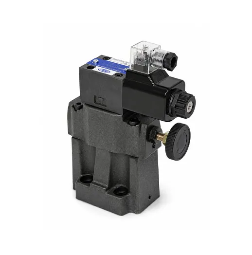
A directional valve should not be confused with a pressure control valve. A directional control valve changes the path of hydraulic fluid, while a solenoid-operated pressure relief valve limits or unloads hydraulic system pressure. Both may use electromagnetic control, but they perform different functions within the hydraulic circuit.
A Common Misunderstanding: Valve Failure Isn’t Always Electrical
When a solenoid-operated hydraulic cylinder stops responding, technicians often inspect or replace the solenoid coil first. A failed coil is one possible cause, but it is not the only one.
A contaminated or mechanically stuck spool can produce the same visible symptom as a damaged coil. Incorrect voltage, a loose connector, low hydraulic pressure, blocked return flow, damaged seals, pilot-pressure loss, or a malfunction elsewhere in the hydraulic control system can also prevent normal movement.
These checks help narrow down the actual cause before replacing components:
- Verify the coil voltage at the connector.
Measure voltage while the controller is commanding the hydraulic valve to shift. No voltage at the connector usually points to an upstream electrical problem involving the PLC output, relay, fuse, wiring, connector, or control circuit. Correct voltage at the connector directs attention toward the coil, armature, spool, pilot circuit, or hydraulic supply.
- Confirm that the coil specification matches the control circuit.
The installed coil must match the machine’s specified voltage and electrical type. An incorrect coil may fail to shift the valve, overheat, or suffer premature damage. Because Baishicheng does not publish one universal coil voltage for this valve line, the project specification and valve identification should be checked directly.
- Listen or feel for the valve shifting.
An audible or tactile click can indicate that the solenoid armature is moving. However, a click alone does not prove that the main spool has completed its stroke or that hydraulic fluid is flowing through the intended path.
- Check whether the manual override operates the valve.
If the valve includes a manual override, testing it can help separate an electrical problem from a hydraulic or mechanical problem. This test should only be performed under safe machine conditions because manually shifting the valve may move the actuator unexpectedly.Inspect hydraulic pressure and return conditions.
A working solenoid valve cannot move an actuator correctly if the hydraulic pump is not producing adequate flow, a pressure relief valve is opening prematurely, the return line is blocked, or the hydraulic cylinder is mechanically overloaded.Check the hydraulic fluid and filter condition.
Contaminated fluid is a common cause of spool sticking and internal wear. Fine particles can enter the small clearance between the spool and valve bore, restricting movement and producing intermittent operation. Fluid cleanliness is especially important for valves installed in a hydraulic control manifold or precision automation system.
- Inspect for overheating and excessive duty cycle.
A warm solenoid coil is not automatically defective, but abnormal temperature, discoloration, damaged insulation, or a burnt odor may indicate incorrect voltage, excessive continuous energization, poor heat dissipation, or internal coil damage.
- Check the connector, seals, and surrounding area for moisture or leakage.
Loose electrical connectors and damaged seals can expose the coil connection to water, oil, vibration, or corrosion. External hydraulic leakage may also indicate a damaged seal, loose mounting surface, or installation problem.
Slow actuator movement does not always indicate a defective directional valve either. A common cause of slow actuation of hydraulic components is insufficient pump flow, excessive internal leakage, a clogged filter, incorrect flow-control adjustment, cold or unsuitable hydraulic fluid, or excessive load.
The valve should be replaced only after the electrical command, coil condition, spool movement, hydraulic pressure, flow path, and contamination level have been evaluated.
| Type |
Positions |
Typical Behavior at Rest |
Common Use |
| 4/2-way directional valve |
2 |
Returns to a defined operating position or remains in the selected position, depending on the actuator arrangement |
Simple forward-and-reverse actuation without a separate center position |
| 4/3-way, closed-center |
3 |
P, T, A, and B are blocked in the center position |
Circuits requiring isolated actuator lines; additional load-holding protection may still be required |
| 4/3-way, open-center |
3 |
Ports are interconnected according to the spool symbol, allowing low-resistance circulation |
Open-center hydraulic circuits and applications requiring reduced pump loading at neutral |
| 4/3-way, tandem-center |
3 |
P connects to T while A and B remain blocked |
Fixed-displacement pump circuits where the pump unloads while the actuator ports remain isolated |
| 4/3-way, float-center |
3 |
A and B connect to T while P is blocked |
Applications where the actuator must move or float under an external force |
| Double-solenoid directional valve |
2 or 3 |
Two coils command opposite spool positions |
Automated equipment requiring electrical control in both directions |
| Single-solenoid spring-return valve |
2 or 3 |
Returns to the defined normal or center position when de-energized |
Circuits requiring a predictable default state after the control signal is removed |
| Pilot-operated directional valve |
Varies |
Main spool position is controlled through a pilot stage |
Hydraulic systems requiring higher flow than a direct-acting valve can practically control |
The hydraulic schematic symbol should always be reviewed instead of selecting a valve from its “4/3” or “4/2” description alone. Two valves with the same port and position count may have completely different center functions, actuation methods, spring arrangements, pilot requirements, or fail-safe behavior.
Pros and Cons of Solenoid Control vs Manual Directional Valves
Solenoid-operated hydraulic valves support remote, repeatable, and automated fluid control. A PLC, relay, sensor, or machine controller can command the valve without requiring an operator to stand beside the hydraulic equipment.
This makes solenoid control suitable for production machinery, industrial automation systems, hydraulic presses, machine tools, material-handling equipment, mining machinery, test equipment, and custom manufacturing lines.
Key advantages include:
- Remote electrical control
- PLC and automation integration
- Repeatable switching sequences
- Compact installation in hydraulic manifolds
- Faster integration with sensors and interlocks
- Reduced need for mechanical operating linkages
- Compatibility with automated safety and process logic
- Easier coordination of multiple hydraulic actuators
The main tradeoff is dependence on the electrical control system. A broken wire, failed relay, damaged connector, incorrect coil voltage, power loss, or control-system fault can prevent the valve from shifting.
A manual hydraulic directional valve does not depend on an electrical signal and can provide direct local control. However, it normally requires an operator at the machine and is less suitable for fully automated sequences, remote operation, or repeated PLC-controlled movement.
Some industrial hydraulic systems combine both approaches. An electro-hydraulic control valve may include a manual override for commissioning, maintenance, or emergency operation. The presence of a manual override does not automatically make the circuit safe during a failure. Machine risk analysis must define what happens to the pump, actuator, stored pressure, and suspended load when electrical or hydraulic power is lost.
The choice between solenoid and manual control should consider:
- Required level of automation
- Operator access
- Switching frequency
- Response requirements
- Available electrical control system
- Environmental exposure
- Emergency operating procedure
- Maintenance capability
- Desired power-loss behavior
- Hydraulic circuit complexity
- Need for manifold integration
For a custom hydraulic build, the valve should be selected as part of the complete system rather than as an isolated component. Pump type, hydraulic power unit capacity, actuator characteristics, hydraulic manifold design, filtration, cooling, sensors, PLC logic, and pressure-control components all influence valve performance.
Baishicheng integrates hydraulic valves with custom hydraulic systems, hydraulic power units and HPUs, hydraulic cylinders, manifold blocks, electric motors, and automation controls for industrial applications.
FAQ
Q: What is a hydraulic solenoid valve?
A: A hydraulic solenoid valve is an electrically operated hydraulic control valve that uses an electromagnetic coil to shift a spool. The spool opens, blocks, or redirects hydraulic fluid between different ports to control a cylinder, hydraulic motor, or another actuator.
Q: How does a solenoid-operated directional valve work?
A: When the coil receives the correct electrical signal, it generates a magnetic field that moves an armature and shifts the valve spool. The new spool position connects different pressure, return, and actuator ports, changing the direction of hydraulic fluid flow.
Q: What does “4/3-way” mean on a hydraulic solenoid valve?
A: It means the valve has four ports and three spool positions. The third position is the center position, which may use a closed-center, open-center, tandem-center, or float-center configuration.
Q: What is the difference between a 4/2 and 4/3 hydraulic valve?
A: A 4/2-way valve has four ports and two positions, while a 4/3-way valve adds a third center position. The center position allows the circuit to hold the actuator, unload pump flow, or let the actuator float, depending on the spool design.
Q: What is the difference between an open-center and closed-center hydraulic valve?
A: A closed-center spool blocks the ports in neutral. An open-center spool provides interconnected flow paths in neutral according to its hydraulic symbol. This difference affects pump loading, heat generation, actuator behavior, and energy use.
Q: Can a closed-center directional valve safely hold a suspended load?
A: A closed-center spool isolates the actuator ports, but internal leakage may still allow gradual movement. Safety-critical load holding normally requires a dedicated load-holding device such as a pilot-operated check valve or counterbalance valve selected for the circuit.
Q: Why did my solenoid valve stop working even though the coil tests correctly?
A: The spool may be contaminated, stuck, worn, or unable to shift because of inadequate pilot pressure. Low pump flow, a blocked return line, damaged wiring, excessive load, or another hydraulic component can also produce the same symptom.
Q: Why is my hydraulic solenoid valve getting hot?
A: Solenoid coils can become warm during normal operation, especially when continuously energized. Abnormal overheating may indicate incorrect voltage, excessive duty cycle, poor heat dissipation, internal electrical damage, or an unsuitable coil specification.
Q: What happens if a hydraulic solenoid valve loses power?
A: The result depends on the valve arrangement. A spring-return valve moves to its normal position, a spring-centered valve returns to center, and a detented valve may remain in its last position. The hydraulic schematic must be checked to confirm the actual fail-state behavior.
Q: Is a solenoid directional valve the same as a hydraulic pressure relief valve?
A: No. A directional valve controls where hydraulic fluid flows. A hydraulic pressure relief valve limits or unloads circuit pressure. Baishicheng supplies both solenoid-operated directional valves and solenoid-operated pressure relief valves within its hydraulic components line.
Q: How do I select a hydraulic directional control valve?
A: Confirm the circuit function, number of ports and positions, center configuration, coil voltage, flow requirement, working pressure, port or mounting interface, hydraulic fluid, electrical connector, manual override, installation conditions, and required behavior during power loss.
Q: Does Baishicheng supply solenoid-operated directional valves as standalone products?
A: Solenoid-operated directional valves are included in Baishicheng’s hydraulic components line and can be selected for application-specific system builds. Buyers should submit their voltage, port, flow, pressure, circuit, and control requirements so the appropriate configuration can be confirmed.

 English
  Get a Quote


 September 16, 2026