A steel mill cannot afford unstable pressure, slow cylinder movement, overheating, or sudden hydraulic failures. These problems can stop production and damage costly machinery. A properly engineered hydraulic system for metallurgical machinery solves these risks by providing stable power, precise control, and reliable operation under demanding plant conditions.
A hydraulic system for metallurgical machinery uses pressurized hydraulic fluid to power, move, clamp, lift, push, and control heavy steel plant equipment. A complete system normally includes a hydraulic power unit, pump, reservoir, valves, hydraulic cylinders, motors, filtration, piping, sensors, and control equipment designed for high loads, heat, dust, vibration, and continuous operation.
What Is a Hydraulic System for Metallurgical Machinery?
A hydraulic system for metallurgical equipment is an industrial power and control system designed to move heavy loads through pressurized fluid. It can operate a hydraulic cylinder, rotary actuator, hydraulic motor, clamping device, tilting mechanism, lifting platform, rolling equipment, furnace mechanism, ladle system, or hydraulic press.
Metallurgical machinery places much greater demands on hydraulics than many light industrial machines. Steel production may involve high temperatures, dust, vibration, shock loads, long operating cycles, and large moving masses. The hydraulic equipment must therefore maintain stable system pressure, predictable movement, and safe operation even when working conditions change.
Typical applications include:
- Continuous casting equipment
- Rolling mill machinery
- Steelmaking production lines
- Ladle and furnace equipment
- Metal forming machinery
- Forging equipment
- Steel coil handling systems
- Tilting and lifting devices
- Clamping equipment
- Metallurgical hydraulic presses
- Material handling machinery
- Graphite and electrode processing equipment
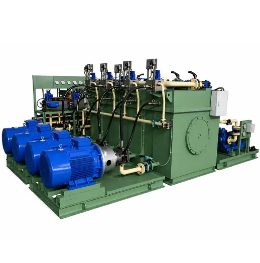
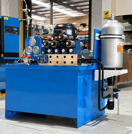
Baishicheng develops hydraulic systems for metallurgical and industrial machinery according to equipment load, pressure, flow rate, cylinder stroke, movement sequence, control accuracy, installation space, and operating environment. Its existing metallurgical systems can integrate the tank, pump station, electric motor, manifold, pipelines, monitoring devices, accumulator, and electrical controls into one platform.
How Do Hydraulic Systems Work in Steel Plant Equipment?
To understand how hydraulic systems work, start with energy conversion.
An electric motor drives a hydraulic pump. The pump moves hydraulic fluid from the reservoir into the hydraulic circuit. Pressure develops when the fluid meets resistance from a load. A valve then directs the pressurized fluid toward a cylinder or another actuator.
The process can be simplified like this:
Electrical Energy → Mechanical Energy → Hydraulic Energy → Hydraulic Force → Machine Movement
For example, when steel plant equipment needs to push a heavy component forward, a directional control valve sends hydraulic fluid into one side of the cylinder. Fluid pressure acts on the piston area. This creates force and moves the piston rod.
When the valve changes direction, oil enters the opposite cylinder chamber and the actuator returns.
Simplified hydraulic power flow
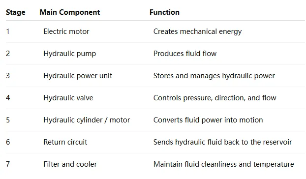
The important point is that a pump mainly creates flow, while resistance to that flow creates pressure. A well-designed hydraulic circuit balances pump capacity, flow rate, actuator size, load requirements, and operating speed.
For metallurgical machinery, these values cannot be selected separately. A larger cylinder may provide more hydraulic force, but it also requires the correct flow if the machine must move quickly. A larger pump may increase available flow, but it can also increase energy consumption and heat if the circuit is poorly matched.
What Are the Main Components of a Hydraulic System?
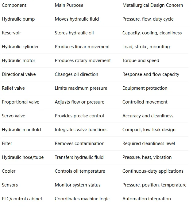
The main components of a hydraulic system work together as one connected power and control network. Choosing one high-quality component does not guarantee reliable performance. Pumps, valves, cylinders, hydraulic fittings, hoses, filters, manifolds, sensors, and controls must all match the operating conditions.
Core hydraulic system components
The hydraulic power unit is normally the central source of hydraulic power. It may contain the reservoir, motor, piston pump or vane pump, hydraulic valve block, filtration, cooler, accumulator, pressure instrumentation, and electrical control components.
Baishicheng also supplies custom hydraulic manifolds and valve block solutions for industrial systems. A hydraulic manifold can reduce external piping, organize flow paths, integrate several valve functions, and simplify equipment layout.
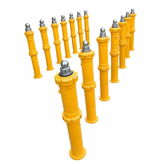
How Should a Hydraulic Cylinder Be Selected for Heavy Equipment?
The hydraulic cylinder is often the part that directly moves the machine. In metallurgical machinery, cylinders may lift, push, clamp, position, tilt, tension, open, close, or support very heavy loads.
Correct cylinder selection starts with force.
A simplified relationship is:
Cylinder Force = Fluid Pressure × Effective Piston Area
But force alone is not enough. Engineers must also consider:
- Required stroke
- Working pressure
- Push and pull force
- Movement speed
- Mounting arrangement
- Side load
- Rod diameter
- Cylinder body strength
- Operating temperature
- Duty cycle
- Seal material
- Position feedback
- Corrosion exposure
- Impact loads
- Installation dimensions
A standard hydraulic cylinder may work well for general machinery, but steel plants often need custom hydraulic cylinder solutions. A custom hydraulic cylinder can be designed around the exact mounting points, load direction, stroke, available installation space, sensor requirements, and environment of the original equipment.
Baishicheng manufactures custom hydraulic cylinders for industrial equipment as well as other hydraulic actuator configurations. Its broader cylinder range is designed around factors such as stroke, load, mounting structure, and operating conditions.
Single-acting vs. double-acting hydraulic cylinders
A single acting hydraulic cylinder uses hydraulic pressure to move in one direction. Gravity, a spring, or an external force returns it.
Double-acting hydraulic cylinders use hydraulic pressure in both directions. This arrangement usually provides better control for industrial machinery because both extension and retraction can be powered.
For steel plant equipment manufacturing, double-acting designs are common where controlled motion, repeatable positioning, or high force in both directions is required.
Why Is the Hydraulic Power Unit Critical to Metallurgical Machinery?
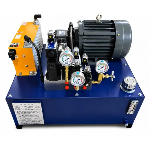
A hydraulic power unit, sometimes called an HPU, hydraulic power pack, hydraulic pump station, or hydraulic station system, supplies the oil flow and pressure needed by the machinery.
A basic HPU may contain:
- Hydraulic tank
- Electric motor
- Hydraulic pump
- Coupling
- Pump inlet
- Relief valve
- Hydraulic valve
Hydraulic manifold block
- Pressure gauge
- Filter
- Cooler
- Level indicator
- Temperature sensor
- Accumulator
- Control cabinet
The HPU must be sized for the complete machine instead of only one actuator. Engineers need to calculate how many cylinders or hydraulic motors may work at the same time, their required speeds, peak pressure, cycle time, expected heat generation, and reserve capacity.
Steelmaking equipment can place especially high demands on the power source. Baishicheng’s hydraulic power unit for steelmaking equipment is designed for applications such as continuous casting machines, rolling mills, turning equipment, and ladle slide gate systems. The configuration can be matched to pressure, flow demand, actuator quantity, control logic, installation layout, and site conditions.
A custom hydraulic power unit is especially useful when standard hydraulic power packs cannot meet the machine’s space, pressure, flow control, cooling, automation, or maintenance requirements.
How Do the Hydraulic Pump, Valve, and Circuit Control Machine Motion?
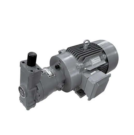
A hydraulic pump determines how hydraulic fluid enters the circuit. Common industrial options include piston pumps, vane pumps, and gear pumps.
Each has different operating characteristics. A variable displacement piston pump, for example, can adjust its displacement as operating requirements change. This can be useful in an advanced hydraulic system where the machine requires different flow levels during different parts of its cycle.
Valves manage what happens to that oil.
Common valve functions
Directional control valves determine where the oil goes.
Pressure valves control or limit pressure.
A relief valve helps protect the circuit from excessive system pressure.
Flow control valves influence actuator speed.
Proportional valves provide variable electronic control over pressure or flow.
A servo valve can support highly responsive and accurate control when the application demands precise movement.
This becomes important when a metallurgical machine needs more than simple ON/OFF movement. Rolling, positioning, clamping, tensioning, testing, or automated forming equipment may need a proportional hydraulic system or servo system for smoother control.
The entire hydraulic circuit should be designed as one system. Incorrect valve sizing may restrict flow. Undersized hose or hydraulic steel tubing may increase pressure loss. Poor manifold design can make maintenance harder. Incorrect pump selection may waste energy and create excess heat.
This is why complex hydraulic systems require engineering rather than simply assembling individual hydraulic components.
What Causes Common Hydraulic System Failures?
Most hydraulic system failures do not begin with one dramatic event. Small problems often develop over time.
A seal starts leaking. A filter becomes restricted. Oil temperature rises. Air enters the suction line. A hose deteriorates. Water enters hydraulic oil. A valve starts sticking. Eventually, the machine slows down or stops.
Common hydraulic failures and possible causes
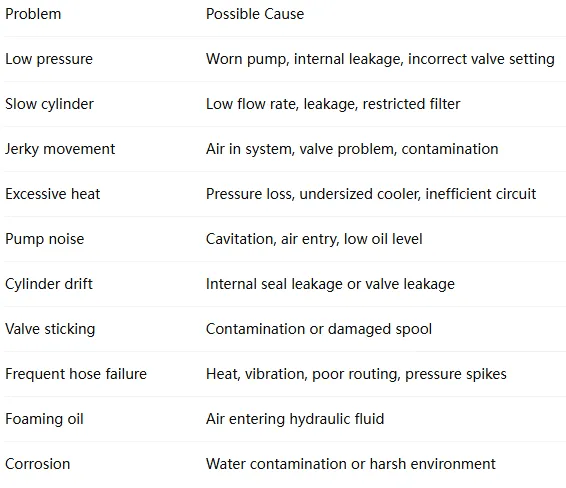
A good troubleshooting method starts with the symptom and then checks pressure, flow, temperature, oil condition, electrical signals, valve operation, and actuator behavior in a logical sequence.
Do not simply replace the first component that looks suspicious.
For example, a cylinder that moves slowly does not always mean the cylinder has failed. The real cause may be insufficient pump flow, a restricted filter, internal valve leakage, incorrect pressure setting, excessive fluid temperature, or a PLC command issue.
This system-level thinking is especially important in large steel production lines.
Why Is Contamination So Dangerous to Hydraulic Equipment?
Contamination is one of the biggest threats to industrial hydraulics.
Particles can enter during manufacturing, installation, maintenance, new oil filling, hose replacement, component wear, or through the surrounding environment. Water and air can also damage hydraulic fluid performance.
The contamination can lead to sticking valves, premature pump wear, sluggish operation, temperature problems, and production line reliability issues. Its oil-management guidance also highlights the sensitivity of modern proportional valves, servo valves, and piston pumps to fluid cleanliness.
Solid particles, water, entrained air, and varnish as equipment-damaging contaminants that filtration and fluid-conditioning systems are designed to remove.
This matters even more in metallurgical plants. Dust is common, machines may work continuously, and hydraulic systems may be installed close to high-temperature processes.
Main contamination controls
- Filter new hydraulic fluid before filling
- Keep the hydraulic fluid reservoir closed and clean
- Use suitable return and pressure filtration
- Replace filters based on condition and service requirements
- Keep hydraulic fittings clean during installation
- Protect hose ends before assembly
- Monitor water in hydraulic oil
- Inspect seals and breathers
- Flush new or modified pipelines
- Use condition monitoring where appropriate
In practice, cleanliness requirements should match the most contamination-sensitive components in the system.
What Does Hydraulic System Maintenance Include?
Good hydraulic system maintenance focuses on prevention.
Waiting until the machine stops is expensive, especially when one system hydraulic station supplies several pieces of steel plant equipment.
Daily or routine checks can include:
- Oil level
- System pressure
- Oil temperature
- Leakage
- Abnormal noise
- Pump vibration
- Hose condition
- Cylinder rod condition
- Filter indicators
- Cooler performance
Periodic maintenance may involve hydraulic oil analysis, filter replacement, accumulator checks, cylinder seal inspection, valve testing, pipeline inspection, sensor calibration, and checking electrical or PLC control signals.
The correct interval depends on operating hours, environment, load, hydraulic technology, machine importance, and manufacturer recommendations.
Predictive maintenance can go further. Pressure sensors, temperature sensors, position sensors, particle monitoring, and PLC data can help operators see changes before failure becomes severe.
For a steel mill, this can be far more valuable than treating every breakdown as an isolated event.
Why Do Steel Plants Need Customized Hydraulic Systems?
A standard hydraulic package works well when machine requirements are simple and predictable.
Metallurgical equipment is often different.
The equipment may require large cylinders, unusual movement sequences, high pressure, variable speed, redundant pumps, special cooling, remote operation, pressure holding, synchronized cylinders, position sensing, or integration with an existing automation platform.
A custom hydraulic system can be designed around:
- Required force and load
- Working and peak pressure
- Cylinder bore and stroke
- Target movement speed
- Required flow rate
- Number of actuators
- Duty cycle
- Available installation space
- Ambient temperature
- Dust and contamination exposure
- Cooling requirements
- Control accuracy
- PLC communication
- Safety logic
- Maintenance access
This is where customized hydraulic engineering becomes valuable.
Instead of asking, “Which hydraulic power unit is already in the catalog?” the better question is:
“What hydraulic configuration does this machine actually require?”
Baishicheng approaches industrial projects from this equipment-level perspective. The company combines hydraulic, pneumatic, mechanical, PLC, servo, and variable-frequency technologies for equipment upgrades and automated production lines. Its website specifically identifies metallurgical machinery, graphite equipment, machine tools, mining equipment, environmental machinery, and production line automation among its industrial application areas.
When Are Advanced Hydraulic and Ultra-High-Pressure Solutions Needed?
Not every metallurgical application needs extremely high pressure.
Many systems should use only the pressure needed to complete the work safely and efficiently.
However, specialized pressing, extrusion, testing, forming, clamping, or compact high-force applications may require far greater pressure than conventional industrial hydraulic machines.
Baishicheng has developed 120 MPa ultra-high-pressure hydraulic systems and cylinders for specialized industrial projects requiring very high hydraulic force.
At these pressure levels, design and manufacturing become even more critical. The hydraulic cylinder body, seals, fittings, tubing, manifold, valve selection, stress calculations, connections, and safety controls must all be engineered for the required pressure class.
The same principle applies to servo hydraulics and proportional control.
Advanced hydraulic technology should not be added simply because it sounds more sophisticated. It should solve a real process requirement.
Use a proportional or servo-controlled system when the machine truly needs features such as:
- Smooth acceleration and deceleration
- Accurate positioning
- Controlled pressing force
- Variable flow
- Pressure profiles
- Synchronized movement
- Closed system feedback
- Automatic process adjustment
Correct technology is better than unnecessary complexity.
How Should Equipment Manufacturers Select a Hydraulic System Supplier?
For machinery OEMs, steel plants, and system integrators, buying hydraulic equipment is not just a component purchasing decision.
It is an engineering decision.
A supplier should understand how the hydraulic system interacts with the original equipment, mechanical structure, electrical controls, process sequence, and site environment.
Before requesting a quotation, prepare as much of the following information as possible:
- Equipment type
- Application
- Required working pressure
- Maximum pressure
- Required flow
- Cylinder quantity
- Cylinder bore and stroke
- Push/pull force
- Movement speed
- Hydraulic motor requirements
- Duty cycle
- Installation dimensions
- Oil specification
- Ambient temperature
- Cooling method
- Electrical voltage/frequency
- PLC requirements
- Servo or proportional control requirements
- Drawings
- Photos of existing equipment
- Special safety requirements
A capable manufacturer of hydraulic systems should use this data to calculate and configure the system instead of forcing a standard product into an unsuitable application.
At Baishicheng Hydraulic, we focus on customized industrial hydraulic solutions for machinery OEMs, equipment manufacturers, engineering contractors, system integrators, distributors, and industrial end users.
Our scope can include the hydraulic station, cylinder, manifold, hydraulic components, tubing, automation interface, and control integration. The goal is simple: build the hydraulic solution around the machine.
For buyers who need a complete project-specific solution, see our Hydraulic System for Metallurgical Equipment or send us your equipment drawings, operating sequence, load, working pressure, and control requirements.
FAQs
What hydraulic equipment is commonly used in a steel mill?
Steel mills may use hydraulic power units, hydraulic cylinders, pumps, valves, hydraulic manifolds, accumulators, hydraulic motors, hydraulic presses, filters, hydraulic tubing, hoses, coolers, and automation controls. The exact equipment depends on the production process.
What is the difference between a hydraulic power unit and a hydraulic system?
A hydraulic power unit mainly generates and manages hydraulic power. It usually contains a motor, pump, reservoir, filters, and control components. A complete hydraulic system also includes the actuators, cylinders, motors, piping, valves, sensors, and other equipment that perform the machine’s work.
What causes hydraulic cylinder failure in heavy machinery?
Common causes include contaminated hydraulic fluid, damaged seals, excessive side loading, incorrect alignment, pressure spikes, worn cylinder surfaces, heat, corrosion, and unsuitable cylinder design. Correct sizing and installation are as important as component quality.
What type of hydraulic pump is used for metallurgical machinery?
The answer depends on system pressure, required flow, duty cycle, efficiency, noise, and control requirements. Piston pumps are often suitable for demanding high-pressure industrial systems, while vane pumps and gear pumps can serve other applications. Engineers should select the pump from actual machine requirements rather than product type alone.
How can hydraulic failures in steel plant equipment be reduced?
Start with correct system design. Then maintain clean hydraulic oil, proper filtration, correct pressure settings, suitable operating temperature, good hose and tube routing, regular inspections, and planned maintenance. Monitoring pressure, temperature, contamination, and actuator behavior can also identify developing problems earlier.
Can an existing steel plant hydraulic system be upgraded?
Yes. Existing systems can often be improved by replacing outdated pumps or valves, redesigning manifolds, upgrading filtration, adding cooling, introducing proportional or servo control, installing position sensors, updating PLC controls, or replacing old cylinders. The existing machine and circuit should be evaluated before deciding which changes are practical.

 English
  Get a Quote


 August 13, 2026