Baishicheng Hydraulic Engineering Team | Technical Content Contributor | Published September 2026
A machine tool hydraulic system supplies pressurized oil to functions the spindle motor cannot handle directly — tool clamping, tailstock positioning, fixture clamping, ram or table feed, and counterbalance — coordinated through a dedicated power unit, valves, and control logic built around the machine’s cycle.
Step 1: Map Every Hydraulically Actuated Function on the Machine
Before sizing anything, list every function on the machine that will run on hydraulic power rather than the spindle drive or a pneumatic circuit. On CNC boring, milling, and turning centers, that list commonly includes tool clamping and release through a draw-bar cylinder, tailstock advance and retract, turret or fixture clamping, ram or table feed, and spindle-box counterbalance to offset a vertical head’s own weight.
Each function needs its own line item: required force or torque, stroke or travel distance, cycle speed, and how often it fires per part cycle. A tool-clamping cylinder that fires every tool change behaves very differently, from a duty-cycle standpoint, than a tailstock that moves once per job setup. Treating them as interchangeable at this stage is where sizing mistakes usually start.
Done when: every hydraulic function has a written force, stroke, and cycle-frequency value — not a placeholder like “TBD” or “standard.”
Step 2: Set Pressure and Flow Requirements per Function
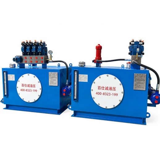
With forces and strokes listed, convert each into a required pressure and flow at the actuator, then check what that means at the pump. Force determines the minimum pressure for a given cylinder bore; stroke speed determines flow. A common misconception at this step is assuming the power unit must be sized for every function running at once. In practice, tool clamping, tailstock movement, and fixture clamping on a single-spindle machine rarely overlap in the actual part cycle, so sizing for simultaneous peak demand across every circuit usually results in an oversized, more expensive power unit than the machine’s real duty cycle requires.
Done when: a pressure and flow figure exists for each function, plus a sequencing chart showing which functions can genuinely occur together.
Step 3: Decide Between Independent Circuits and a Shared Manifold
Two architectures cover most machine tool builds. Independent circuits give each function its own valve bank and are simpler to troubleshoot in isolation, at the cost of more plumbing and panel space. A shared manifold consolidates several functions onto one block with individually controlled sections, which is more compact and easier to keep leak-free across many connection points, but requires more careful design so one circuit’s transient pressure spike doesn’t disturb another.
For a machine with more than three or four hydraulic functions, a manifold-based approach is generally the more maintainable choice; for one or two simple, infrequent functions, independent circuits can be the lower-effort path. This is a project-specific decision, not a fixed rule.
Done when: the architecture is chosen and documented with a reason tied to function count and duty cycle, not just cost.
Step 4: Specify Control Logic and Interlocks
Machine tool hydraulic functions rarely run in isolation from the machine’s control system. Tool clamping needs to confirm clamped or unclamped state before the spindle is allowed to start or the tool changer is allowed to move. Tailstock position needs feedback before a turning cycle begins. Fixture clamping typically needs a pressure switch or position sensor confirming clamp force before the cutting cycle is enabled.
List each interlock as an explicit condition: what signal is required, what it blocks if absent, and what happens on signal loss mid-cycle. A hydraulic circuit that performs correctly on the bench but has no defined behavior for a dropped clamp signal during a cut is an incomplete specification, not a finished one.
Done when: every safety-relevant function has a documented interlock condition and a defined fault response, reviewed against the machine’s PLC logic.
Step 5: Define Testing and Commissioning Requirements
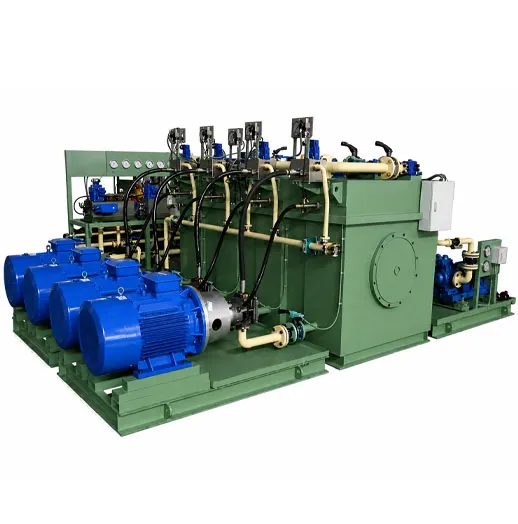
Before a hydraulic system for a machine tool ships or is accepted, it should be tested at full operating pressure and full flow, not just at a reduced bench-test condition. Compared with a system that is only spot-checked at partial load, full-pressure and full-flow testing before commissioning is more likely to surface a marginal seal, an undersized line, or a valve that sticks under real load rather than after installation on the shop floor.
Baishicheng’s disclosed manufacturing workflow for custom hydraulic systems includes full-pressure and full-flow testing along with pre-shipment commissioning, and factory witness testing is available on request for buyers who want to observe acceptance testing directly rather than rely on a test report alone.
Done when: a test plan exists covering every function at its rated pressure and flow, with acceptance criteria written down before testing starts — not decided during the test.
Step 6: Plan for Serviceability Before the Machine Ships
A hydraulic system that is difficult to service costs more over the machine’s life than one that costs slightly more to build. Filter and fitting access, clear labeling on each circuit, and a documented schematic matching the as-built system all belong on the specification, not left as an afterthought for the maintenance team to reverse-engineer later.
For applications rated well beyond conventional hydraulic pressure, Baishicheng also lists engineering capability up to 120 MPa. That figure applies to specially engineered systems and cylinders built for designated ultra-high-pressure applications; it is not the standard operating pressure of a typical machine tool auxiliary circuit, and a machine tool spec should be built from the actual pressure requirement of its own functions rather than referenced against that ceiling figure.
Done when: the service plan, schematic, and labeling scheme are reviewed and signed off alongside the functional specification, not produced after commissioning.
Where This Gets Specific to Your Machine
Baishicheng’s product catalog lists CNC Machine Tool Hydraulic Systems among its published custom system applications, engineered around each project’s control logic, function count, and interface requirements rather than sold as a fixed catalog unit. No standard pressure, flow, or tank-capacity range is published for this system family, since specifications are set per project; buyers working from a specific machine spec should confirm exact figures directly rather than assume a published default applies.
FAQ
What hydraulic functions typically need their own circuit on a CNC machine tool?
Tool clamping and release, tailstock advance and retract, fixture or turret clamping, ram or table feed, and spindle-box counterbalance are the functions most commonly run on a dedicated hydraulic system rather than the spindle drive.
Why shouldn’t a machine tool hydraulic power unit be sized for every function running simultaneously?
Most machine tool functions like tool clamping, tailstock movement, and fixture clamping occur at different points in the part cycle rather than all at once, so sizing for true simultaneous peak demand usually produces an oversized, higher-cost power unit relative to the machine’s actual duty cycle.
How is a manifold-based hydraulic system different from independent circuits?
A shared manifold consolidates several functions onto one block with individually controlled sections for a more compact footprint, while independent circuits give each function its own valve bank, which is simpler to troubleshoot but takes up more panel space.
Why does full-pressure and full-flow testing matter before a machine tool hydraulic system ships?
Testing at full operating pressure and flow is more likely to reveal a marginal seal, undersized line, or sticking valve before installation, rather than after the system is already running on the shop floor.

 English
  Get a Quote


 September 02, 2026