Baishicheng Hydraulic Engineering Team | Technical Content Contributor | Published August 26, 2026
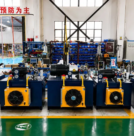
Servo hydraulics uses a closed-loop servo valve or a servo-driven, variable-speed pump to continuously adjust flow, pressure, or position based on real-time feedback, instead of running a fixed-displacement pump at constant output and throttling the excess. It’s used where precision, repeatability, or energy efficiency outweigh the added cost and complexity.
What Is a Servo Hydraulic System?
Every hydraulic circuit needs two things: a way to move fluid, and a way to control it. In a standard circuit, a fixed-displacement pump runs at a set speed and a directional or proportional valve routes flow to the actuator, with any excess flow dumped back to tank through a relief valve. Servo hydraulics changes the control side of that equation by closing the loop — a feedback sensor (position, force, or pressure) continuously reports the actuator’s actual state back to a controller, and the controller adjusts the system in real time to drive the error toward zero.
That correction can happen at two different points in the circuit, and which one matters a great deal for what you actually get out of the system.
Two Ways Servo Control Shows Up in a Hydraulic Circuit
Servo valve on a fixed-speed pump. A low-power electrical command drives a small torque motor inside the servo valve, which shifts a spool to meter high-pressure oil to the actuator in proportion to the signal. A feedback transducer on the actuator reports actual position or force, and the controller trims the command continuously. This is the classic architecture behind precision motion control — test rigs, position-critical machinery, anything that needs to hold a load within a tight tolerance under varying conditions.
Servo-driven (variable-speed) pump. Here the pump itself is driven by an electric motor under servo or VFD control, and the motor’s speed — not a downstream valve — is what varies to match demand. A control unit compares actual system pressure or flow against the target and adjusts motor torque accordingly. Because the pump only produces what the cycle actually needs at each moment, this architecture is where most of the energy-saving case for servo hydraulics comes from.
These aren’t competing options so much as tools for different problems. A servo valve solves a precision problem. A servo-driven pump solves a demand-matching problem. Some systems use both.
Why It Matters: Precision and Energy Efficiency
The precision case is straightforward: closed-loop feedback corrects for load variation as it happens, so the actuator holds position or force even when the load itself is inconsistent — exactly the condition a fixed, open-loop circuit struggles with.
The energy case is less intuitive but often the bigger dollar figure over a system’s service life. A fixed-displacement pump has to be sized for peak demand, but it runs at that same output constantly — including during the parts of the cycle where the actuator is dwelling, decelerating, or idle. All of that unused flow gets throttled or relieved back to tank, and that throttling loss shows up as heat, not useful work. A servo-driven pump avoids most of that loss simply by not producing flow the cycle doesn’t need. The bigger the swing between peak and idle flow demand in your duty cycle, the more that difference is worth.
Fixed-Displacement Circuit vs. Servo-Controlled Circuit
| Dimension |
Fixed-Displacement Circuit |
Servo-Controlled Circuit |
| Pump behavior |
Runs at constant speed regardless of demand; excess flow is throttled or dumped to tank |
Pump speed (servo-driven pump) or valve opening (servo valve) adjusts continuously to match actual demand |
| Precision |
Accuracy depends on valve response and load consistency; no real-time correction |
Closed-loop feedback continuously corrects for load variation |
| Energy behavior at partial load or idle |
Wastes energy as heat through throttling and relief, even when the actuator isn’t moving |
Servo-driven pump architecture cuts energy use during low-load or idle periods |
| Complexity & maintenance |
Simpler circuit; standard valves, fewer sensitive components |
Requires clean oil, tuned control loops, feedback sensors, and integration with a PLC or controller |
| Best fit |
Steady, continuous-duty, lower-precision applications |
Cyclic duty cycles with large flow swings, or applications needing tight repeatability |
Compared with a conventional fixed-displacement circuit, the servo route trades circuit simplicity for demand-matching and repeatability — a trade worth making on the right duty cycle, and not worth making on the wrong one.
Where This Shows Up in Baishicheng’s Published Applications
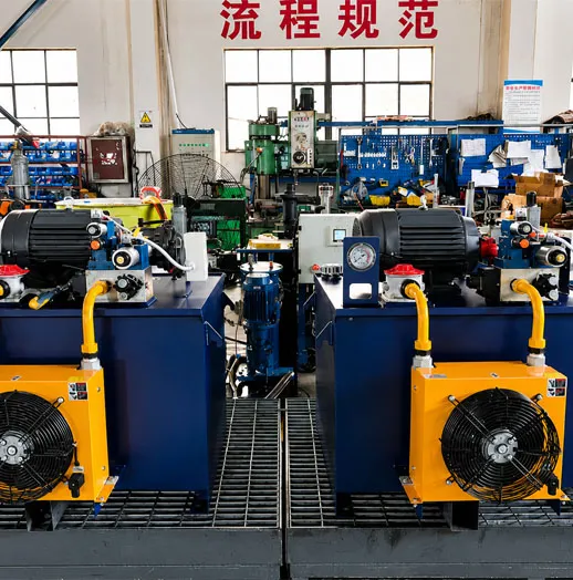
The Forging Press Hydraulic System is one of the representative applications published under Baishicheng’s Custom Industrial Hydraulic Systems line. Forging is a useful reference point for the energy argument above because the duty cycle is inherently cyclic: a high-flow press stroke followed by a return and dwell phase where flow demand drops sharply. That swing between peak and idle demand is exactly the profile where a servo-driven pump architecture earns back its added cost fastest, since a fixed-speed pump sized for the press stroke would otherwise be throttling unused flow through most of the cycle.
No standard numerical pressure, flow, or motor-power range is published for Baishicheng’s custom industrial hydraulic systems as a category — each is engineered to the customer’s own pressure, flow, and control requirements. The company’s engineering capability reaches up to 120 MPa for designated ultra-high-pressure applications, but that figure describes specific engineered systems, not a baseline spec you should assume applies to every custom build, forging-related or otherwise.
The Trade-Off: When Servo Hydraulics Is Worth the Added Complexity
The most common misconception isn’t about whether servo hydraulics works — it’s about which architecture actually saves energy. A servo valve added to an otherwise standard fixed-speed pump improves precision, but it doesn’t by itself reduce energy consumption, because the pump is still producing constant flow and the valve is still metering the excess away. The energy savings specifically come from the servo-driven pump architecture, where the pump’s own output varies with demand. Buyers sometimes assume any system labeled “servo” delivers both precision and efficiency gains automatically; in practice, you get what the specific architecture is built to deliver, not what the word implies.
The complexity is real on both counts, though. Servo valves are sensitive to fluid contamination, so oil cleanliness standards get stricter, not optional. Control loops need tuning, feedback sensors need maintenance, and the servo drive or amplifier has to integrate cleanly with whatever PLC or controller runs the rest of the machine. None of that is a reason to avoid servo hydraulics on an application that genuinely needs it — but it’s a reason to avoid it on one that doesn’t. A steady, continuous-duty, low-precision application usually isn’t worth the added
How to Evaluate Whether Your Application Needs It
- Map your duty cycle. Plot flow demand over a full cycle, not just peak demand. A flat demand curve favors a standard circuit; a cycle with sharp peaks and long idle or dwell periods favors a servo-driven pump.
- Define your actual precision requirement. “Tighter is better” isn’t a spec. Get the real position, force, or pressure tolerance the application needs, and check whether a standard proportional valve can already hit it.
- Check your contamination control. Servo valves are unforgiving of dirty oil. If your current filtration and maintenance practice can’t reliably hold to a servo valve’s cleanliness requirement, budget for that upgrade alongside the valve itself.
- Confirm control integration up front. Identify what protocol your PLC or controller needs to talk to (this is typically a straightforward requirement to state, not a blocker) and raise it with your supplier before design starts, not after the quote.
- Ask how the supplier documents and tests the control loop. A quality-management process matters more here than on a simple fixed-displacement build, because the failure modes are subtler.
Baishicheng’s website displays a Quality Management System Certificate for GB/T 19001-2016 / ISO 9001:2015 (Registration No. 0762203355R05-SD/001, issued by Beijing Zhongrunxing Certification Co., Ltd. for the 2022–2025 certification period); confirm current certification status directly if it matters for your procurement file, since the displayed validity period has already passed its end date.
If your duty cycle has genuine flow-demand swings and your precision requirement is real rather than aspirational, the case for servo control gets easy to make. If neither is true, a standard circuit will do the job for less money and less maintenance overhead.
FAQ
Q: What’s the difference between a servo valve and a servo-driven pump?
A: A servo valve modulates flow to the actuator on a pump that still runs at constant speed, mainly improving precision. A servo-driven pump varies the pump’s own speed to match demand, which is where most energy savings come from.
Q: Does “servo hydraulics” always mean energy savings?
A: No. Precision and energy efficiency come from different parts of the architecture — a servo valve alone improves control accuracy, not energy use; the servo-driven pump architecture is what reduces energy waste.
Q: What kind of duty cycle benefits most from a servo-driven pump?
A: Cyclic applications with a large swing between peak and idle flow demand, such as a process with a high-flow work stroke followed by a return or dwell phase.
Q: Is servo hydraulics overkill for a simple, continuous-duty application?
A: Usually, yes. Steady, low-precision, continuous-duty applications rarely recover the added cost and maintenance burden of a servo-controlled circuit.
Q: Does Baishicheng publish a standard pressure or flow range for its custom hydraulic systems?
A: No. Custom Industrial Hydraulic Systems are engineered to each customer’s own pressure, flow, and control requirements; the company’s 120 MPa capability applies to designated ultra-high-pressure applications, not as a baseline spec.
About the Author
This guide was produced by the Baishicheng Hydraulic Engineering Team, which supports the design, manufacture, testing, and commissioning of custom hydraulic systems, hydraulic power units, hydraulic cylinders, and automation-integrated industrial equipment. The team’s engineering scope covers hydraulics, pneumatics, PLC automation, servo drives, variable-frequency drives, and mechanical integration. Baishicheng Hydraulic was founded in 1995 and has more than 30 years of company-level hydraulic engineering and manufacturing experience — presented here as company and team experience, not the personal history of an individual author.

 English
  Get a Quote


 August 26, 2026